Home Theater Forum and Systems banner
101 - 120 of 169 Posts
Yes, that is correct.

The post I changed to "Nevermind" was in response to something earlier, and as the topic had shifted since then to something similar, but different I decided to remove it before it caused any confusion. I wasn't quick enough it seems. ;)
If this was a concern, perhaps it would be possible to construct better formed arms, ones with a profile more aero dynamic than just a cylindrical one? I can see how this might be stronger, but can also see how once the arm twists the angle of attack is changed and this may be detrimental, even if the arms are stronger as a result of such a shape.
 
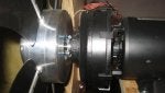
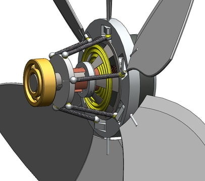
An alternative would be to have the fan connected to the shroud and allow it to rotate with the blades. this would have benefits, A) allow an outboard bearing to support the outer tip (great) B) Increase rotational inertia substantially as hoops are better than solid disks {(1/2M*(Ri^2+Ro^2)) versus just (1/2*M*R^2)} (good), C) Minimize vortice shed at the tips as the blade tip conditions are more controlled/constant with no relative motion (probably not so important). However the detriments are the need for a small gap between the rotating shroud and stationary ducts on either side. This would also increase construction cost and complexity, things Steve doesn't want to hear....

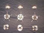
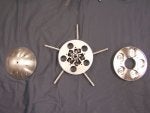
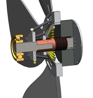
For the blades I tried to think of an cheap and easy way to form the blades in an aerodynamic manner but couldn't think of anything that did both. Seems it could be accomplished by a deep wood block clamshell CNC milled to a zero-lift foil shape, line it with mylar for nonstick, fiberglass it thinly, insert rod, and fill with Great stuff foam. but then you have additional milling. could be done by hand wiht a router and laminated/sanded but I suppose it would take forever. Even this method would probably lead to balance issues unless you were very meticulous with the fiber glass. could always balance later though. however this way the stiff arm is buried inside the foil and has no effect on the aero. Of course milling comes at the cost of about $80-100/hr plus markup on materials=expensive.


also to note is that an aerodynamically formed arm will offer little in terms of additional strength. for lateral loading of a shape like this, the elongation (streamlining) of the arm would be done along the neutral axis and thus not offer any additional strength to resist bending in the plane it would occur. You can google "bending beam stress distibution" to see what I'm talking about. It's a fundamental thought of mechanics of materials, bending stress is zero along the neutral axis. For a squarish beam it's (bh^3)/12 where h is the height of the beam. this simple relation is why I-beams have their shape and floor joists are tall, adding height gives strength at a cubic rate where width is linear. the flange at the outer edges bear the highest stress and that's why there there. the web connecting the two does little in terms of strength, just keeps the outer fibers in place. In this case it would be like making the web thicker and not changing the flanges.

The benefit it would add though is strength to the coupling between blade and axis and (as in the construction mentioned above) keep the blade from breaking free of the arm and hopelessly flopping about (the arm would twist inside the blade).
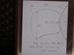
 
I was curious as tho the linkage being used and thought it may be a rack and pinion like Steve has come up with. It looks like the blades "spines' are straight shafts inserted through the hub with collars set screwed to them. The collars probably have a threaded hole toward the periphery for maybe a rod end type joint.

Steve

If this is the case it seems like the assembly may be simpler that you had proposed. I never was sure how you planned to affix the pinions to the shaft. From this pic it appeard that the only thing that would need machining is the hub itself and the shafts, collars, and such could be purchased although I'm unsure about the rod end type joints. There are very small, I'm guessing these are of the RC hobby type.

Seems like the rack and pinion would be a more robust design. From my experience with machines and equipment, set screw type retainage seldom works well (stripping and "wallered" shafts that won't disassemble), but in this case maybe the forces are small enough it doesn't matter.

ROTFAN

What is the tuning procedure for the fan? I thought somewhere I read the speed is adjusted to room size. also what is the diameter of the fan? What size motor is used? I was curious how all of this relates to output as the blade configuration has a fairly low solidity and it seems like much could be had from a few design tweaks. If designing I would think they would have went for a little more blade area to increase output and reduce the required fan speed (noise) at the same time.
 
memarcus: The motor controller is used to adjust the speed of the rotating fan. Adjusting
the speed compensates for the size of the listening room volume. My room
is 29' long x 19' wide x 11' high cathedral ceiling and I use considerably less
than the maximum speed. What also comes into play is the rear volume that
the rotary subwoofer is venting into. ( I vent into my very large basement, which is
over 2000 sq. ft. The smaller the back venting the lower the efficiency (lower
output). The higher the speed the more fan noise is generated, so that is also
something to consider. With my large enclosure (8' long x 4' wide x 4' high) and
lined with 6" fiberglass on all the interior surfaces and the speed that I use, the
fan noise is negligible. The diameter of the fan blades is 19", and the motor
is 1/3 hp. Moving on, the size of the vent opening into one's room is also very
important. A minimum of 3' x 3' is required, 4' x 4' would be better, 5' x 3'
would suffice. A ratio of 1:1 is best, so I used 4' x 4'.
 
Hi
Very nice cad drawings !
You are planning to rotate the whole assembly.. from what i can see (?) - maybe you would look for a wheel hub assembly , to interface with the motor. (Those can be had for a budget...)
btw.. what is the use for the bearing in front ?
Frank
 
thanx, and yes i`m planning to rotate the whole assembly. I thought this way, i could translate the liniear movement of the coil more directly to a rotating movement for the blades.
The drawing is still a concept drawing, so it isnt thoroughly tought out.
The reason for the ballbearing is that i can show u that from that end the assembly rotates. (still have to draw the motor, etc)
In witch way would you apply the wheel hub assembly?
I`m still looking for a donor subwoofer, witch i can use for its parts (motor, voicecoil and spider) When i have those, a can make the final design and start machining some parts
 
great CAD. I suspect you'll need to do some serious rework in conjustion with the rod end bearings. Although RC helicopters parts are small and I've seen parts of this type of project use them I think they would be an expensive option. Also I'm not sure they'd handle the forces involved. you have to remember they're desinged for a totally different fan configuration with very low solidity.

Seems rotating the whole thing causes some issue. A) the elctrical connection. Seems if done properly this could be expensive and if not done propoerly, noisy. Either way would probably incur maintenance issues. B) rotating the mortor structure is a lot of weight. This may requirea torqier motor and starting caps and such. Thinking on this through Steve's design it seems a linear slide bearing that allows rotation is the cheapest and easiest to source solution I could come up with to decouple the rotation and linear motion.

Also I suggest trying to not pitch the blades more than 15 degrees if possible. From my research on the aero it seems that's the best range to avoid BL separation and the ensuing noise. If possible I would also shoot for a non lifting foild rather than flat blade also but that gets expensive/difficult to construct.
 
101 - 120 of 169 Posts